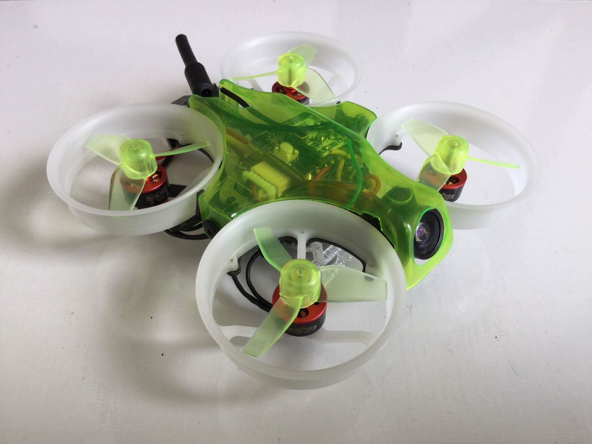
 The antenna of a top-mounted camera is prone to breakage. A low-profile design reduces that risk. It also allows you to hit smaller gaps (as skills permit) and look cooler, too. Here’s how to build a low-profile brushless whoop.
Parts and Equipment
For this build, I used the following:
- Rakonheli 66mm Brushless Whoop frame
- Rakonheli 31mm 1mm shaft 3-blade clear propellers
- X-Racer X-1 frame
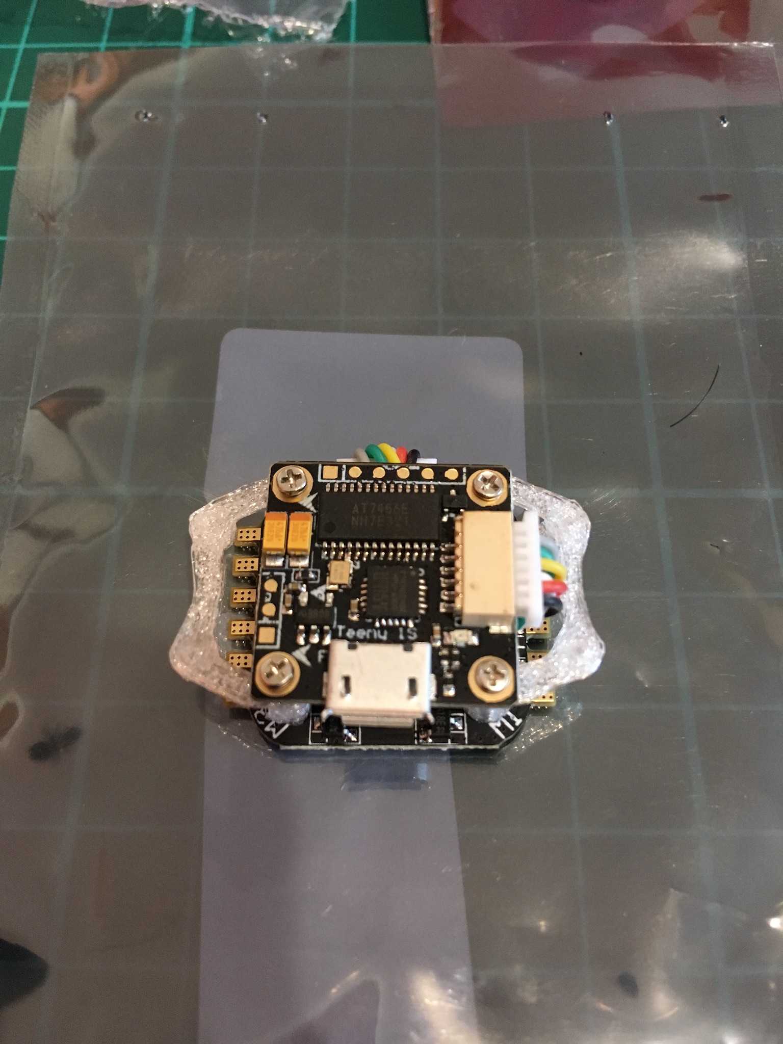
- Teeny1S F4 Flight Controller with Teeny1S 4-In-1 6A ESC
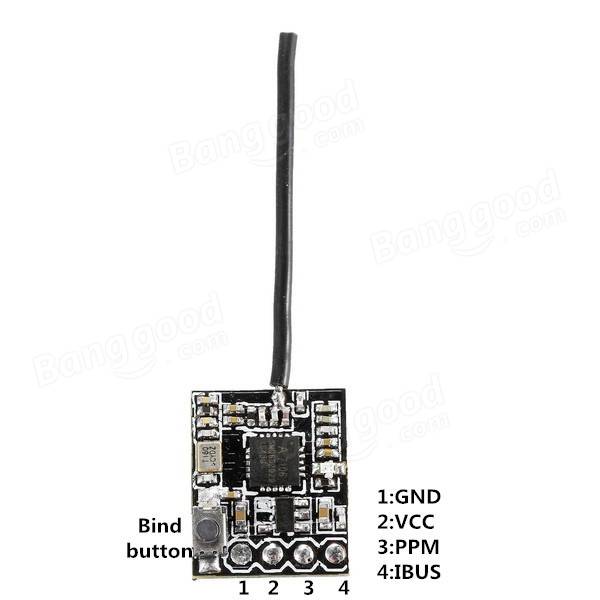
- Flysky RX2A Pro Receiver
- Turbowing Cyclops 2 5.8G 48CH 25mW VTX
- Kingkong 800TVL 150 degree FOV camera
- Racerstar BR0703 Racing Edition 15000KV Motors
- Soldering iron
- Soldering wire
- Desoldering pump
- Flux
- Wire snips
- Double-sided tape
Build Procedure
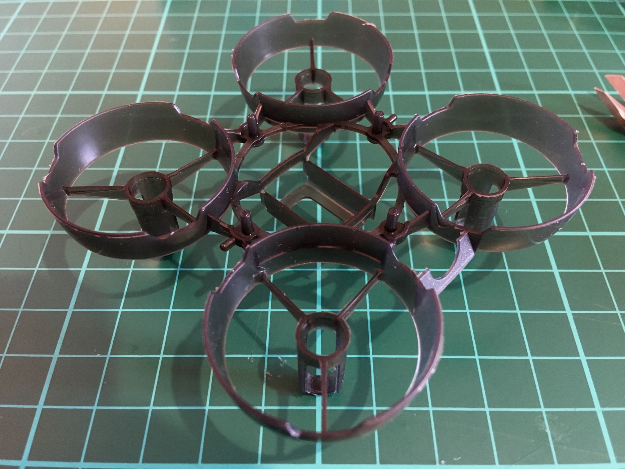
- Remove the camera mount and the canopy pins from the donor X-Racer X-1 frame
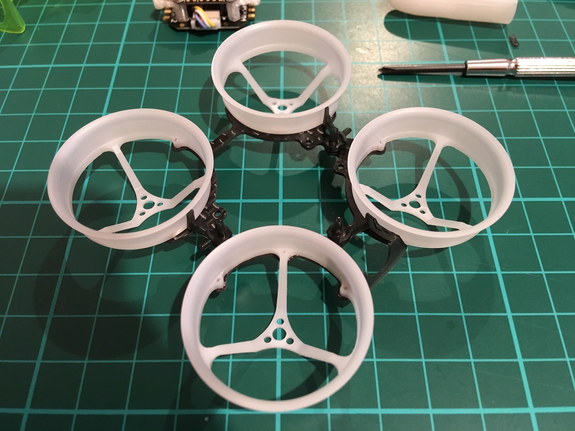
- Assemble the frame. There are lots of tiny screws of different sizes. A vernier caliper will come in handy
- Lay out the FC and the ESC. Ignore the standoffs and screws included in the FC and ESC package and use the screws included with the Rakonheli frame kit.
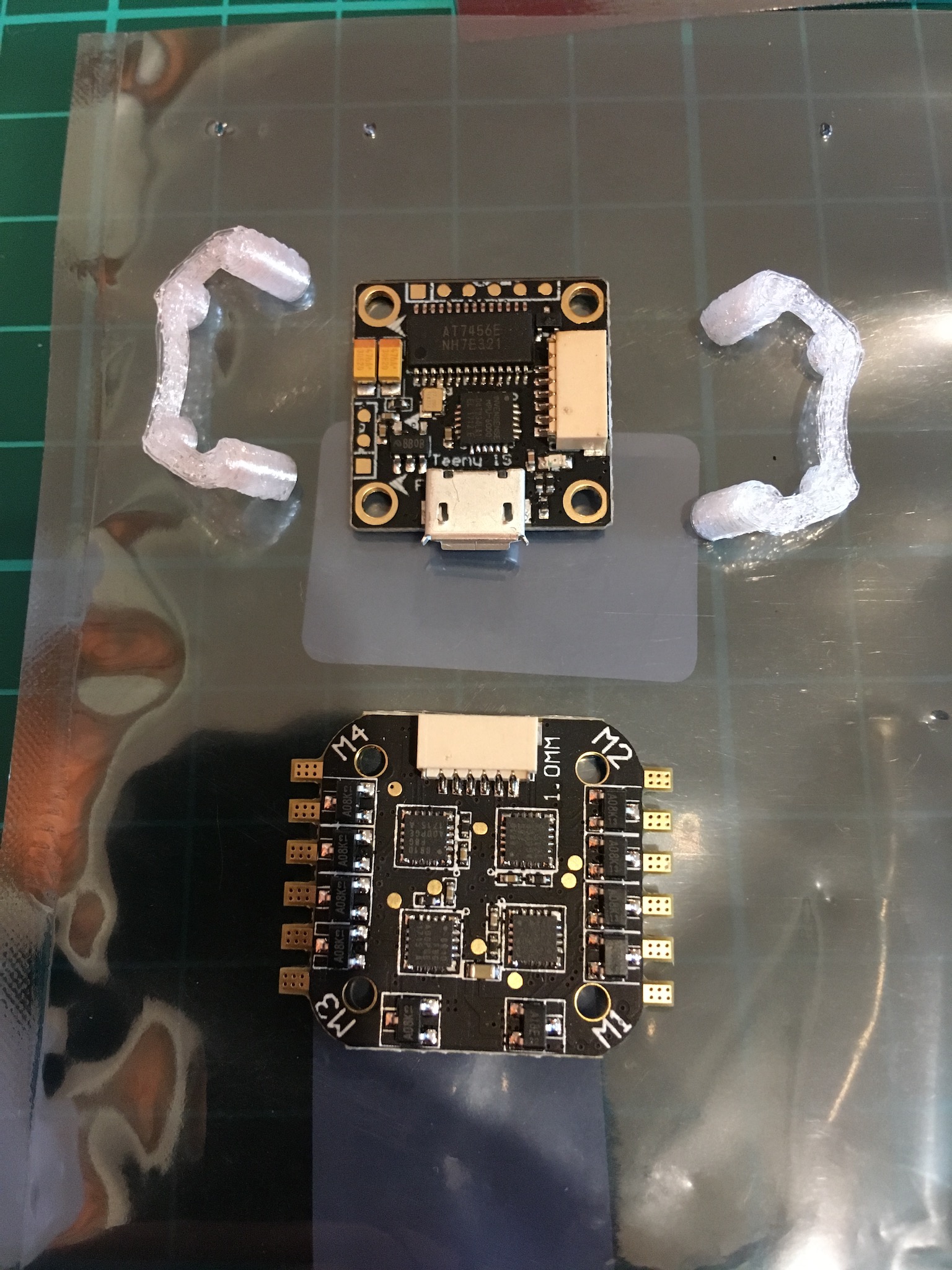 Note the FC is not facing forward. This is so that the USB port will be accessible. We will need to configure orientation to -90 yaw in Betaflight.
 - Plug in the FC-to-ESC harness and assemble the FC and ESC stack.
 When mounting the ESC and FC together using the metal screws, if the screws touch, it may cause a short. Best to use nylon screws. If you have to use the metal screws, shorten them. Finally use multitester to see that there’s no continuity on the corresponding screws of the FC and ESC.
 - Review pad layout

- Solder the RX wires to the FC
- Solder the AIO camera wires to the FC.
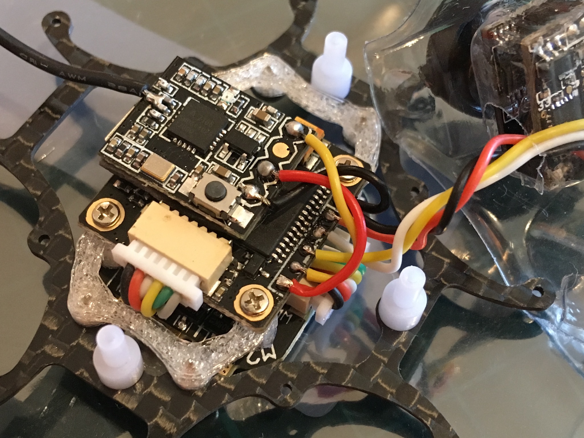
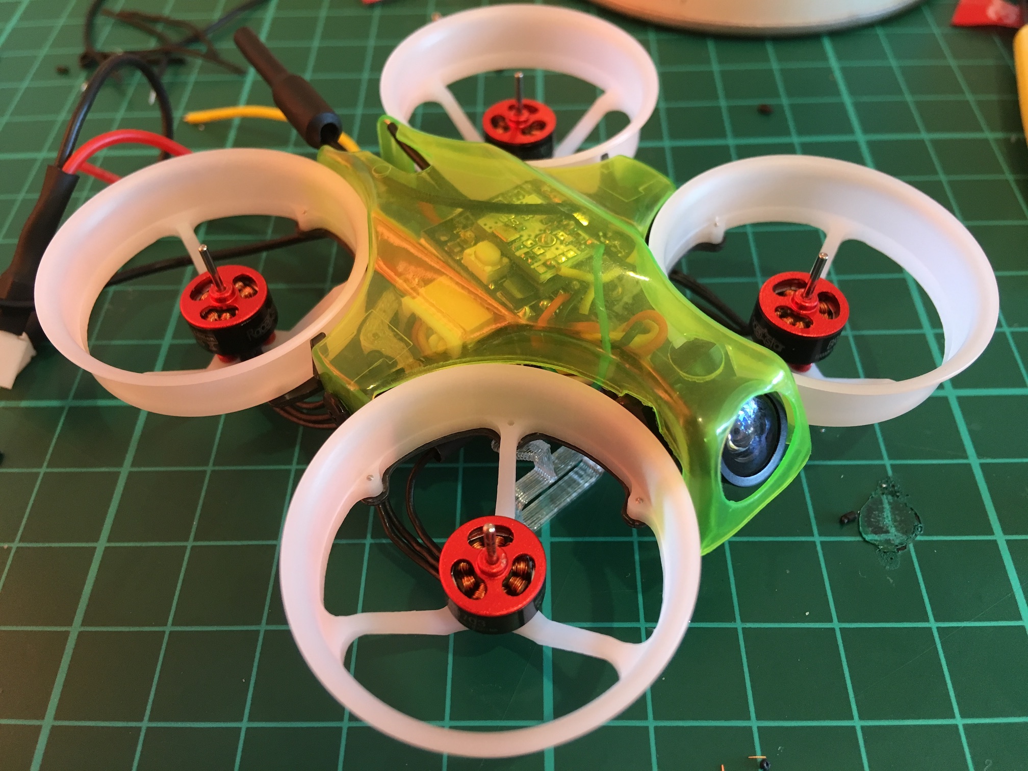
- Mount the stack onto the frame
- Mount the motors. Ignore the screws included with the motor package (which are too long) and use the screws included with the Rakonheli frame kit.
- Pre-tin the battery pads and solder in the battery connector pigtailÂ
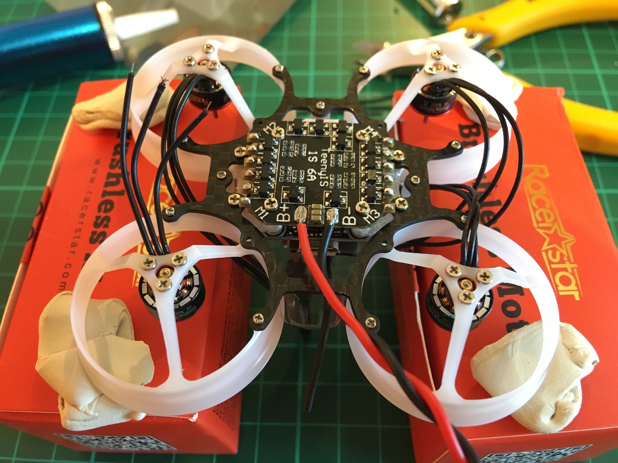
- Pre-tin the ESC pads and solder in the motors wires to the ESC pads
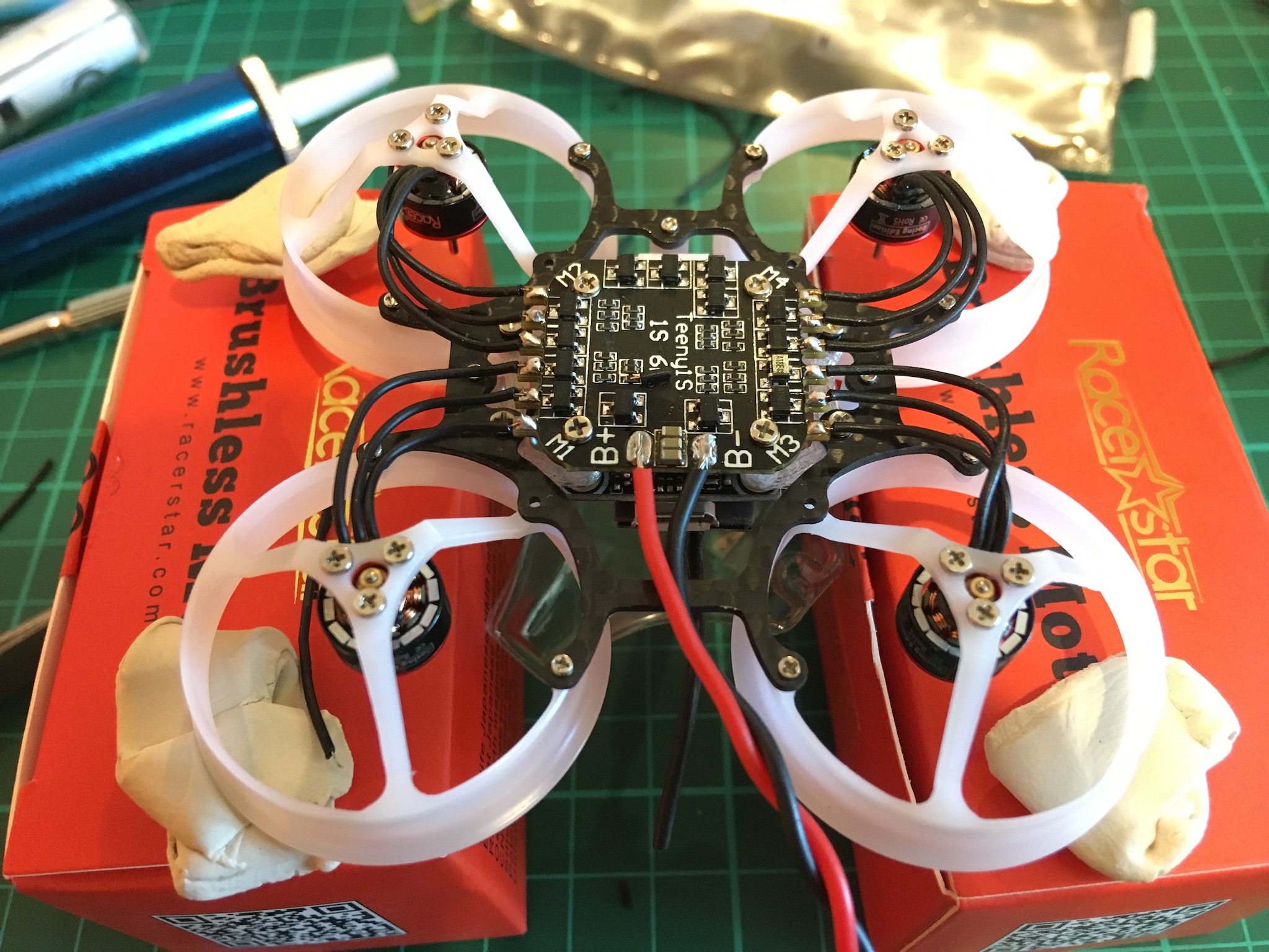 This  is probably the hardest part of the build. You will need to trim the motor wires and strip the ends. Then, set your iron to 400°C, add some solder to the tip and  burn off the copper wire’s coating. Finally, solder with your iron set to 350°C and use flux.
 - Once all soldering is done, check continuity between B+ and B- with a multitester. There should be NO continuity.
- Cross your fingers, plug-in the battery and check for magic smoke
- Install the props
- Done!