When you start thinking (fantasizing?) of being a drone racer, you will want to know how fast you are around your home track: You need a lap timer to record the time elapsed from the time you leave the starting gate to the time you pass it again. There are usually two ways of doing this: attaching a transponder (additional equipment) or using the RF signal of the VTX (no additional equipment). Needless to say, we will be doing the latter approach.
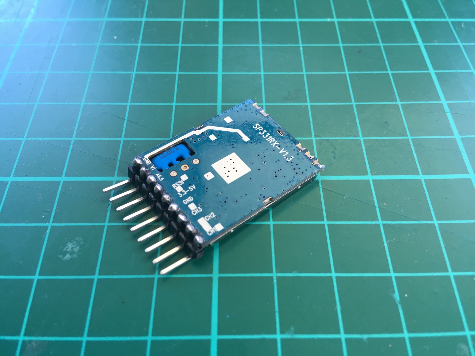
The key component is the RX5808 module which is the heart of most, if not all, video receivers in the market. The module receives the VTX signal and converts it to audio and video. It also measures and provide the signal strength (RSSI value). What the lap timer does is to compare the RSSI with a set threshold. If the RSSI value is above the threshold, the corresponding drone is considered passing a finish gate and the time elapsed is recorded.
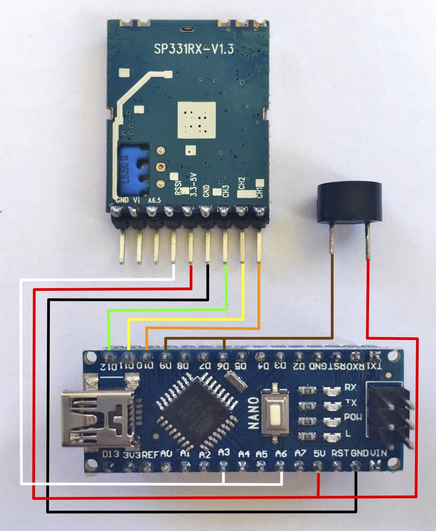
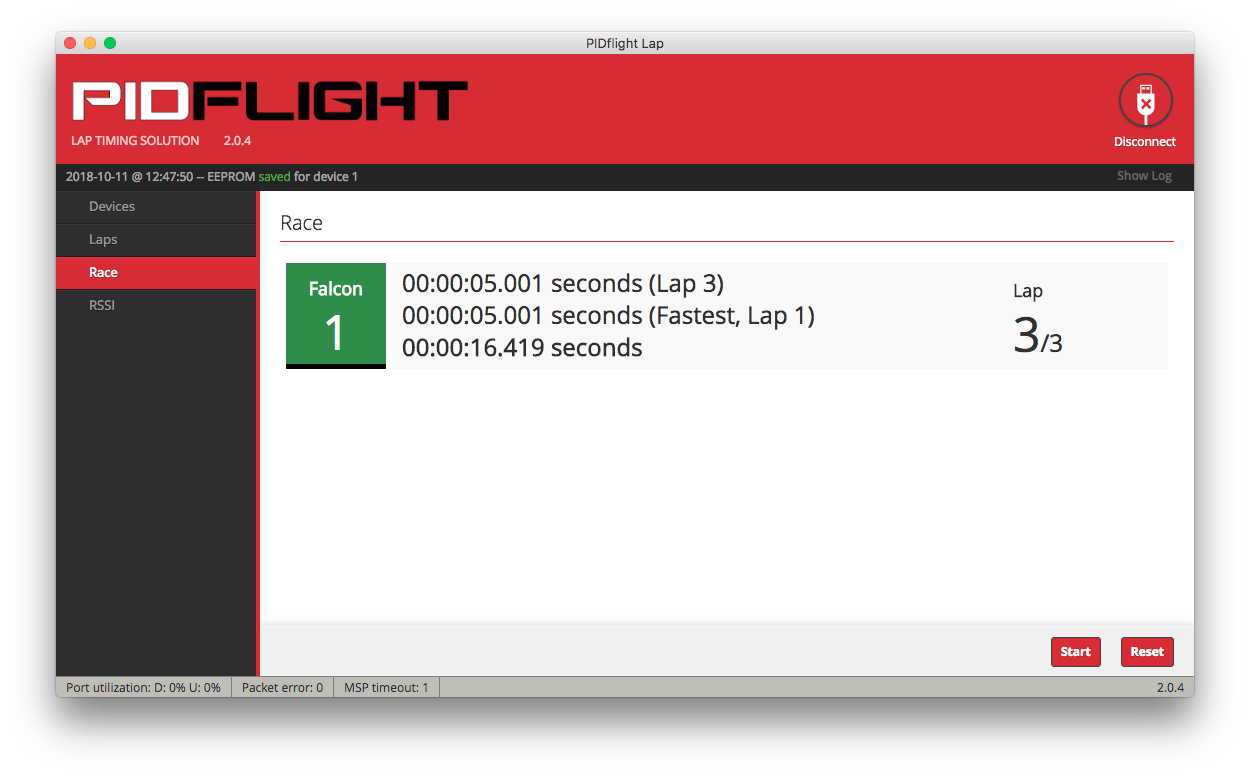
There are two maybe three active lap timer projects online: Chorus RF Laptimer and PIDFlight Lap. For this project, we will adopt the schematic and use the software and firmware of PIDFlight Lap. However, to keep things simple for now, we will simplify the schematic and use connected mode where the lap timer is connected directly to and powered from a computer or Android phone (via OTG).
Parts and Equipment
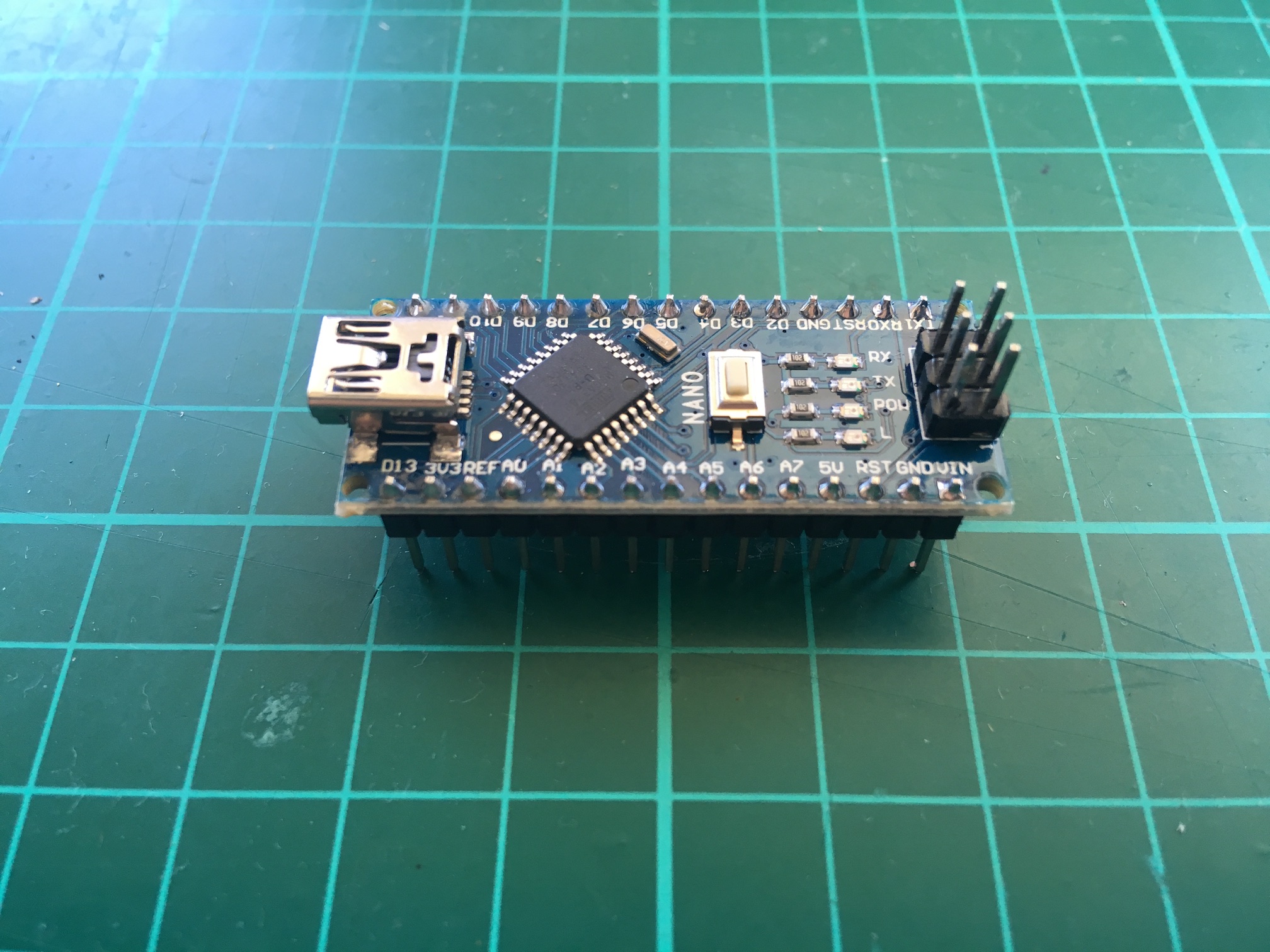
- Arduino Nano V3 or compatible
- RX5808 FPV Receiver Module
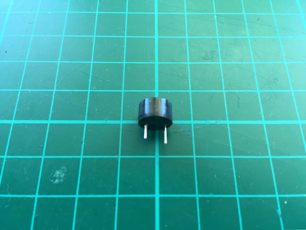
- Buzzer
- Breadboard (or PCB)
- Header pins (and optional header sockets if using PCB)
- Arduino Nano FTDI driver (or CH340/341 driver for clones)
- Arduino IDE
If you’re working with the PCB, you’ll need the following:
- Soldering iron
- Soldering wire
- Desoldering pump
- Flux
- Wire snips
Procedure
- Review revised schematic

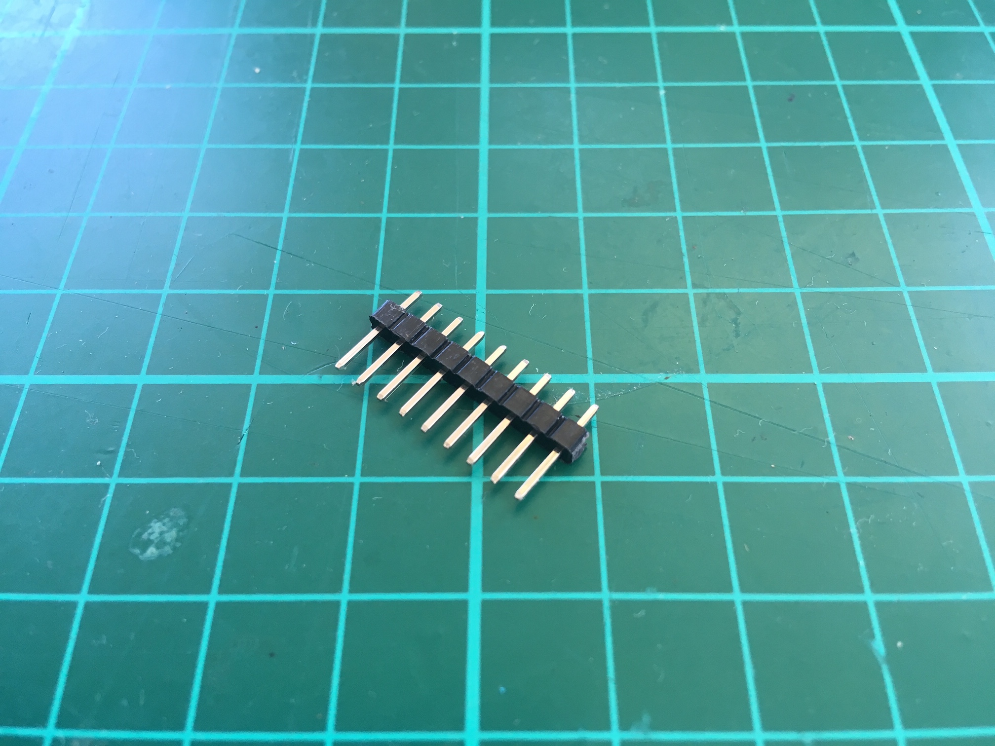
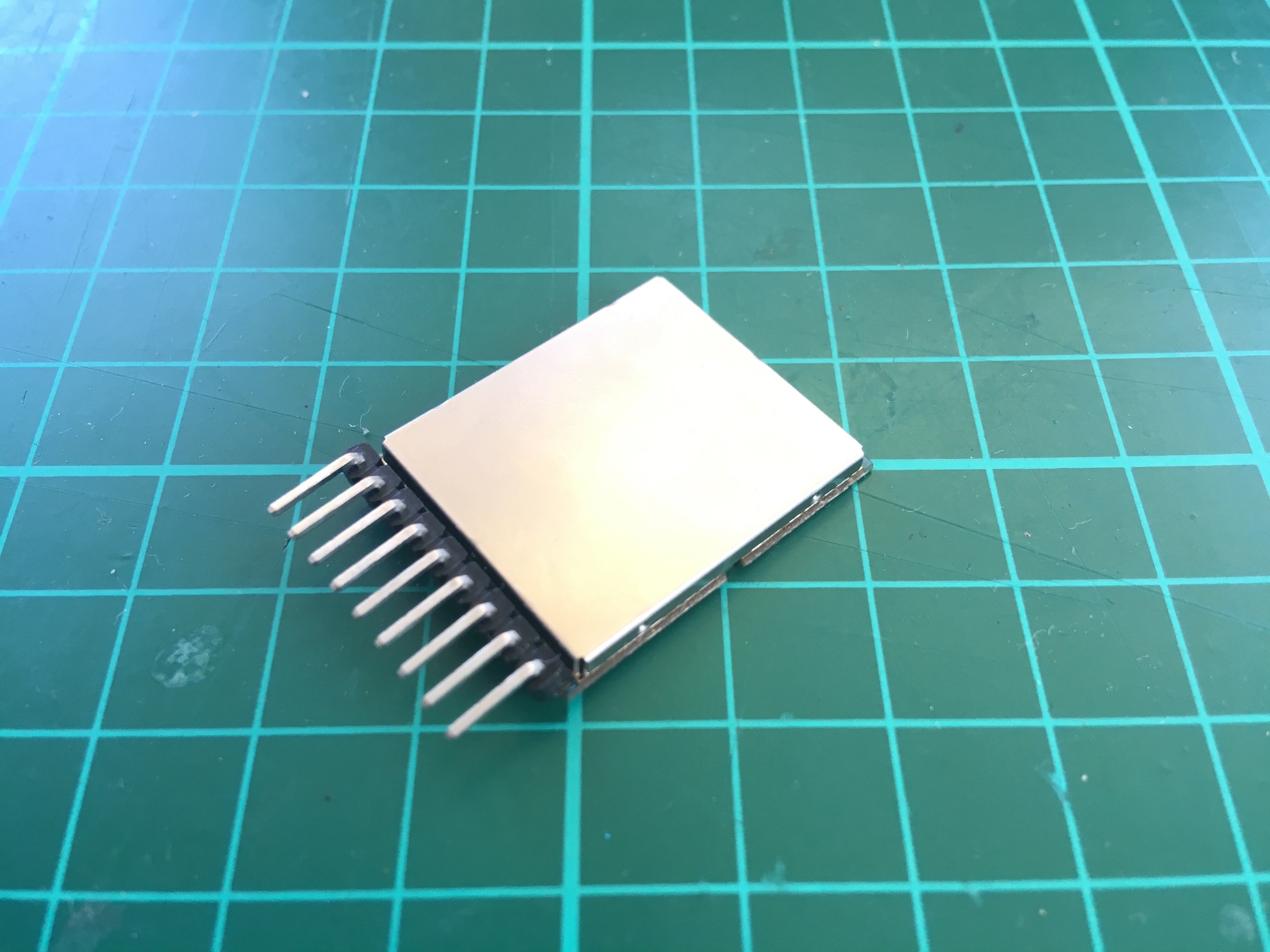
- Prepare header pins for the RX5808 module. You need 9 pins

- Solder header pins to RX5805 receiver module


- Prepare buzzer. The short leg is ground, the long leg is positive. This is also indicated on the top of the buzzer body.
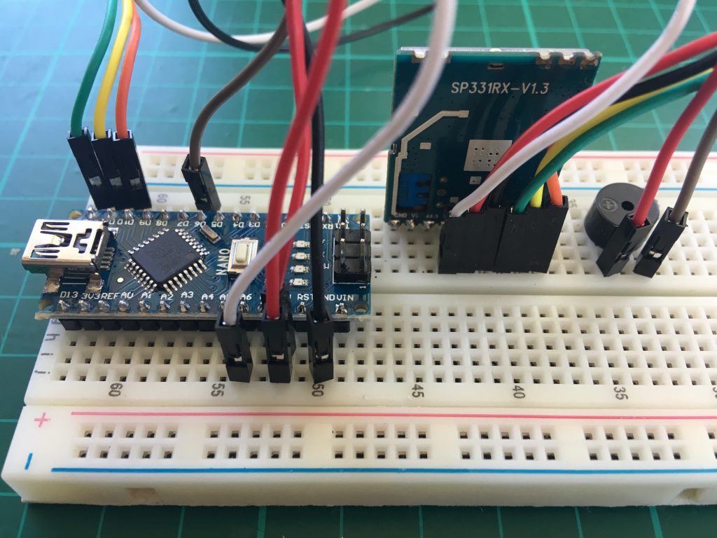
- Following the schematic, insert the components to the breadboard
- Install Arduino Nano driver
- Install Arduino IDE
- Install the appropriate firmware.For Chorus RF Laptimer, you can download the Arduino sketch, load it on the Arduino IDE, and upload to the Arduino nano. For PIDFlight Lap, you will get a .hex file and you will need to upload manually. You can use XLoader on Windows or Hex Uploader on the Mac. Or use avrdude directly:
/Applications/Arduino.app/Contents/Java/hardware/tools/avr/bin/avrdude -C/Applications/Arduino.app/Contents/Java/hardware/tools/avr/etc/avrdude.conf -v -patmega328p -carduino -P/dev/cu.wchusbserial410 -b57600 -D -Uflash:w:pidflightlap_2.2.0_PDFL.hex:i
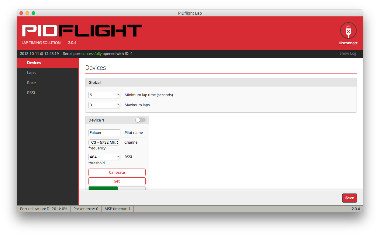
- Install and run the appropriate software.
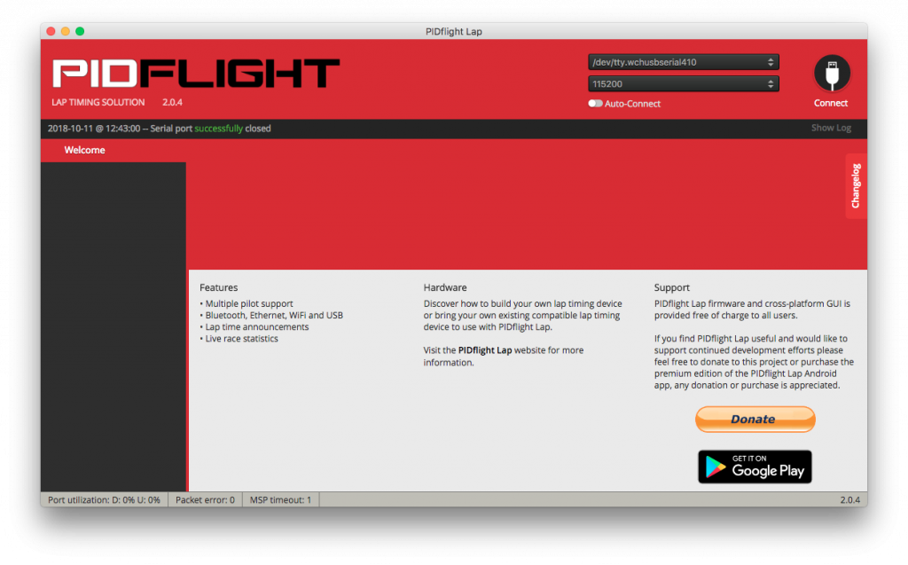
- Connect

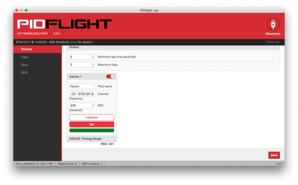
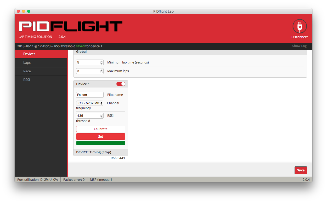
- Activate and calibrate lap timer device for target VTX
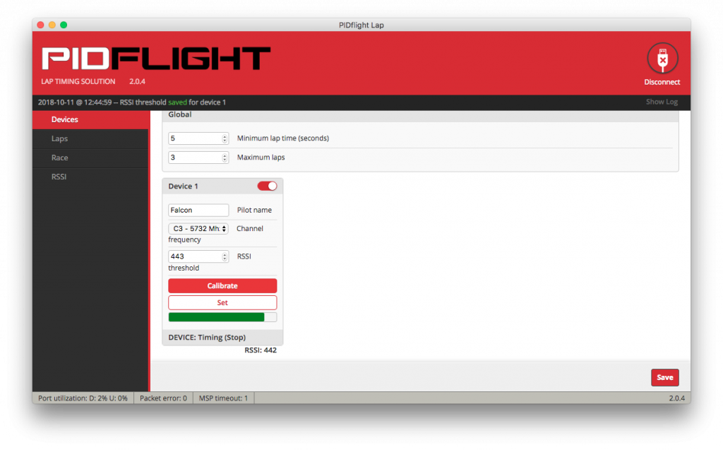
- Set threshold. The higher the threshold, the less sensitive and more precise. The lower, the more sensitive and less accurate.
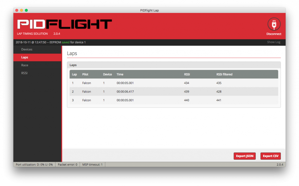
- Race!


